
Modular Roads Take… Twelve? #
I’m back working on a project to re-make some excellent road and terrain tiles I’d bought years ago from a vendor that is no longer in business. This also means opportunities to both enlarge the tiles and eventually add more: I’d previously worked on an overpass at the same scale, and might try to rework that to fit in with these better.
I’ve remade the tiles several times and have lost track. Several dead-ends or just failures to get them looking the way I want.
However I’m running into an issue.
For a proper set of modular terrain I need a minimum of:
- Straight Roads
- 4 Way intersections
- 3 Way intersections
- 90 degree curves
After this I can work on some fun stuff: I’d love to do a big “Traffic circle” element that is essentially a 4 Way intersection with connected elements to allow space for the roads to connect and buildings to be added around the enlarged circle.
I’ve created these several times so far, and it’s been a good learning experience. I’ve found one useful behavior was to essentially make my own ‘primitives’ in the form of plain shapes without detail to get the rough shapes done (booleans and such) then add the final detailing on a second set. I’m seeing one odd issue though I’m not sure how to fix or even the proper way to pose the question.
My Process #
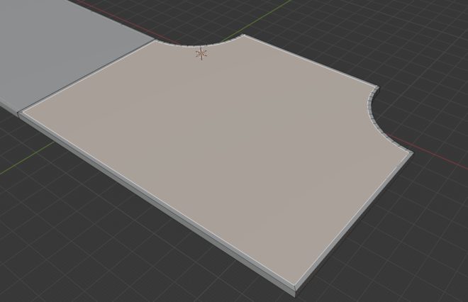
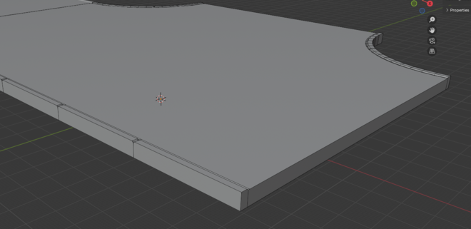
I created my basic “plain’ pieces by using Cube primitives squashed to the appropriate thickness (2mm) and resized and placed. The Straight Road (seen at the upper left of the image) was detailed at half-width and a Mirror modifier applied. However this doesn’t work as well for the other pieces.
My basic detailing is cutting a thin slice along the edge which has a panel line applied via the Panel Cutter add-on . The road bed is then lowered slightly and additional cuts may be added to look like seams in curbs.
For the various curved pieces the Inset tool seems perfect. I start with something like the below:
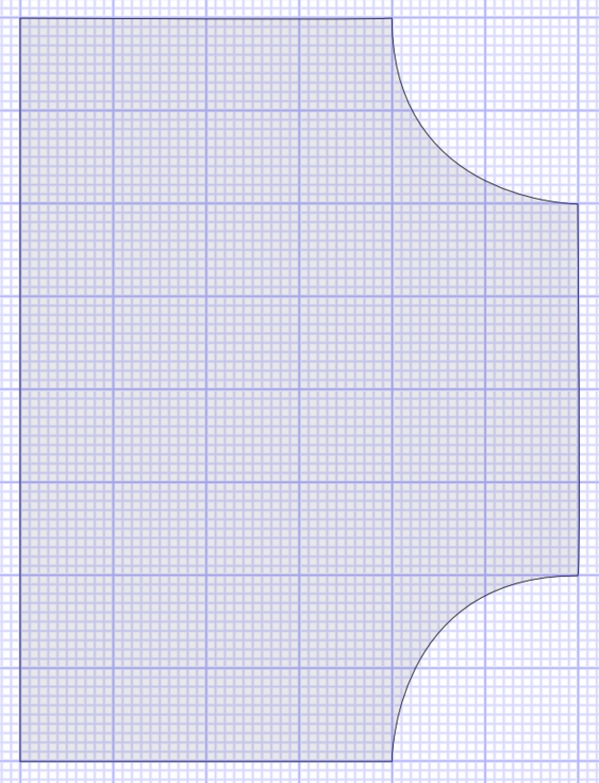
(These images are a mock-up made in Affinity Designer, not the actual Blender output. I can be semi-competent in multiple applications!)
Selecting the top Face in Edit mode and using the Insert option allows me to get something similar to Figure 2, below. Here’s where I find issues. I need the middle Inset face to extend to the edges on the top, right, and bottom of the piece.
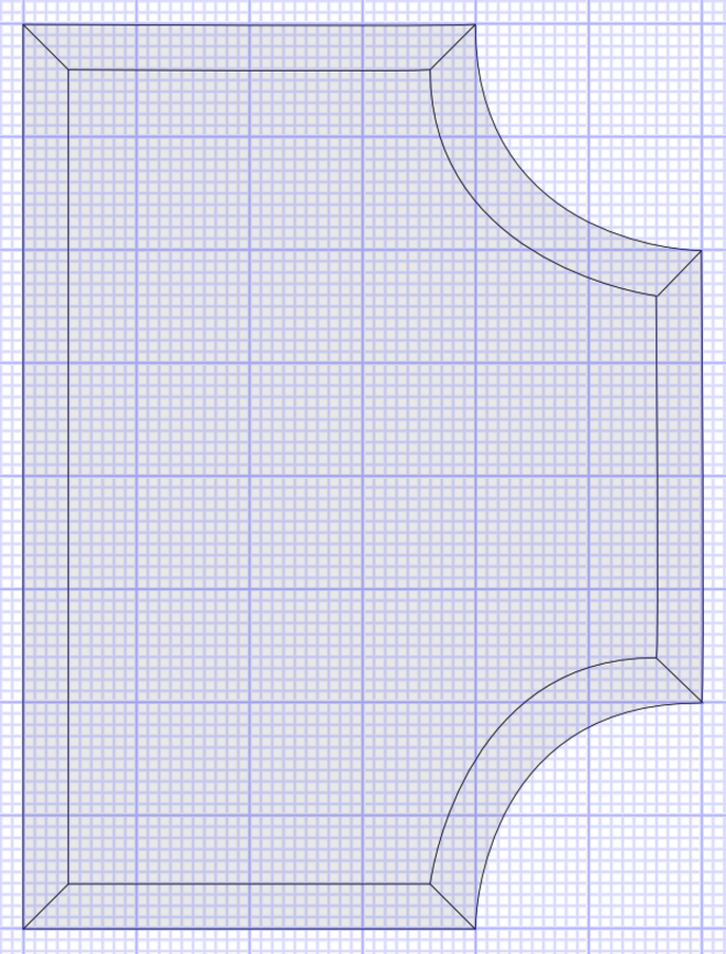
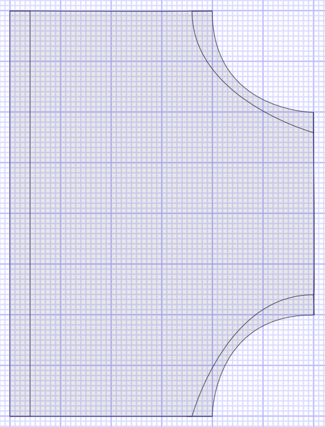
Figure 3 is closer to what I ultimately want. The verison below has severely distorted arcs, which I’d liek to avoid, but in ym case it might not be noticeable to any degree.
In Search of Solutions #
I’ve tried a few things to resolve this issue, but none have been satisfactory. I can move the line in yellow in the below to line up with the outside line and it looks good at first glance, but there’s a mess of hidden geometry that causes issues.
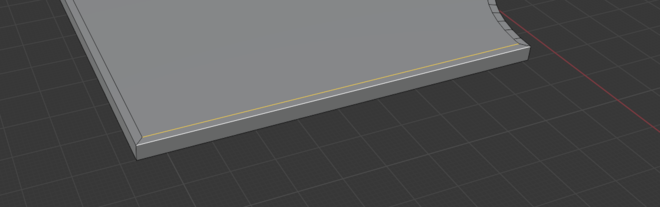
This creates the below, but then when I lower the ‘road bed’ it creates a messy end point and fixing that just got messier.
Going Back a Few Steps #
One thought is I’m going the wrong way with this and need to add geometry by some means instead the Inset function.
The Solution #
I’ve found a possible solution! I received great advice from @Lironah on Mastodon. She advised extruding the end pieces to fix the issue and this may have worked. However, it inspired another way:
Adding to ‘End Cap’ Geometry #
One thing that was advised was that, yes, I should have the geometry of the end pieces detailed so that the outside “curbs” were better marked. I added this to each end cap in what is, I think, arguably the worst way.
My end cap pieces are 50 units wide, and the curbs are about 1 unit
I first tried the Loop Cut tool and specifying the Factor value. For one cut this at �0.95 is perfect… But for the second cut, it’d need to be slightly different as the total width is now different, and the math was unpleasant at best.
My brute force solution was to add 49 equally spaced Loop Cuts to the cap face. Then all but one on each end of the piece was dissolved into a single face. A missed opportunity is dissolving the Vertices as well. Brute force, but it certainly worked.
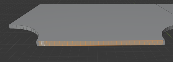
This left some slightly messy bits I had to fix. Mainly, the edges at the top and bottom of the caps were divided into 50 segments.
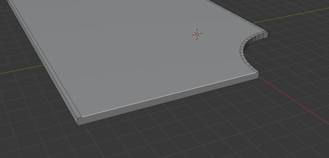
Inset Applied #
The Inset function worked nearly perfectly!
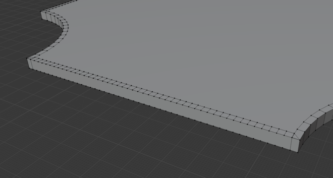
I say nearly because the extra vertices caused some odd issues. On the remaining pieces I’ll try dissolving the the excess vertices down before the Insert command is used, but in this example cleanup was pretty simple. The primary cleanup was to remove the excess faces.
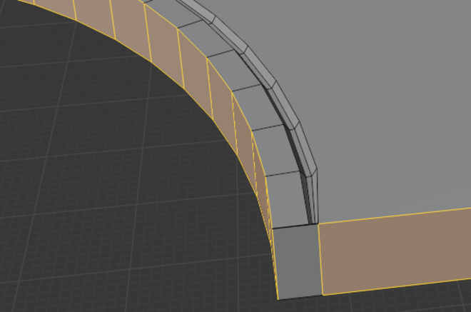
One of the three endcaps did get slightly more complex as shown above. Essentially there was a stray overlapping piece of geometry on each end. To resolve I backed out of the Panel Line and selected the relevant vertices. Merge by Distance solved this issue.
For future elements I’ll definitely try simplifying before the Inset function to make it less challenging on Blender.
It Works! #
Is it the best solution? Probably not. This also was obtainable with basic built-in Blender tools. I do use a Panel Cutter extension to automate cutting grooves as well as some of the UI improvement types, but they really didn’t impact the workflow. (I have other extensions loaded, but they’re really for very specific tasks.)
Next Steps #
Next up is to repeat and refine the process for the corner and four-way elements, then get some test prints made, which may require cleanup for 3d printing.
Thanks again to @Lironah on Mastodon for her patience with my semi-coherent explanations of the issue.